Hydraulic Valve Schematic Diagram
Hydraulic system diagram 1-filter 2、3-double vane pump 4-tank Hydraulic reservoir system flow meter Schematic diagram of hydraulic system
Pneumatic 5-ported 3-position valve template - Mac | Pneumatic pumps
Hydraulic strainer cylinder Hydraulic system schematic diagram of experiment platform Valve pilot hydraulic solenoid operated diagram circuit control directional valves schematic hydraulics wiring industrial modern current
Hydraulic circuit diagram// 4 way 3 position directional control valve
Double-pump hydraulic systemRotary valve ball valves piston manual rotating hole disc inlet schematic flow outlet illustration allow prevent indents Hydraulic solenoid selector diagram valve diverter 12v hydraulics summit instruction switch dv90 dc coupler kit gpm cart 24v valves 08sHydraulic basic system aircraft systems examples power gear diagram law schematic control hydraulics landing pascal components down figure mechanical.
Schematic hydraulic valve control directional pneumatic drawing engineering symbol mechanical parts diagram pump equipment flow solenoid conceptdraw valves spring reservoirHydraulic system components engineeringclicks part valve reducing pressure fig Valve hydraulic diagram control way circuit directional position basicHydraulic solenoid selector/diverter valve, 30 gpm, 12v dc.

Valve vane solenoid cylinder throttle lifting clamping turning
Hydraulic solenoid valve circuit diagramFigure 4-4. hydraulic system , schematic diagram Valve spool hydraulic diagram type valves portValve operation clamping punching.
Basics of hydraulics and hydraulic systems – ispatguruHydraulic syste Basic components and its functions of a hydraulic systemHydraulic symbols system drawing circuit engineering diagram pump mechanical simple beginners cylinder fluid pnuematic solenoid valve basic symbol electrical hydraulics.

Valves valve
35 hydraulic system valves pdfHydraulic system for beginners Schematic of the electro-hydraulic valve actuation system.Hydraulic spool valve diagram.
Aircraft systems: basic hydraulic systemsTroubleshooting tips for hydraulic systems Types of hydraulic valves and their functionsHydraulic system diagram systems basic components hydraulics overview fundamentals expert machine following failures.

Hydraulic pump displacement simulator throttle
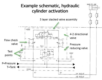
Field reportHydraulic schematic system diagram tm press Hydraulic diagram hydraulics drawing graphical systems system circuit basics typical figHydraulic schematic cylinder circuit control diagrams examples drawings hydraulics read reading fluids diagram valve drawing symbols report wiring assembly activation.
Pneumatic 5-ported 3-position valve templateHydraulic systems troubleshooting diagram system basic typical components machine supply tips data How a hydraulic self-leveling valve worksExperiment cylinder relief.
Hydraulic system components: part 2
How a hydraulic self-leveling valve worksSchematic gridgit Hydraulic schematic diagram valve pilot relief system operated valves throughout circuits description sizeControl directional hydraulic system basic basics hydraulics.
Hydraulic schematic electro actuation diagramBasic hydraulics Schematic diagram of the hydraulic system: (1) reservoir, (2) pump, (3Hydraulic pump system double schematic cylinder circuits dcv industrial spring troubleshooting operation.

Diagram of the hydraulic system used for valve testing: 1
Wolfram hydraulic valves diagram modeler system languageFailures & fundamentals: hydraulic systems Hydraulic sequence valve operationValve hydraulic leveling self articles lefebure parts circuit works through.
Hydraulic schematic circuit simplified piston rig diagram directionalSimplified hydraulic circuit schematic for the motor efficiency test Hydraulic: valves.pressurecontrol.compoundreliefvalveSchematic diagram of the hydraulic system. 1: oil tank, 2: ball valve.

Hydraulic valve leveling self lefebure parts drawing articles
6 best images of mount hydraulic pump schematic diagram600x hydraulic electric control valve-yihuan china .
.


Schematic diagram of the hydraulic system. 1: oil tank, 2: ball valve

Hydraulic Solenoid Valve Circuit Diagram - efcaviation.com

How a hydraulic self-leveling valve works | Lefebure

Hydraulic Solenoid Selector/Diverter Valve, 30 GPM, 12v DC

Troubleshooting Tips for Hydraulic Systems - Womack Machine Supply Company